60 Watt CO2 Laser Cutter
CO2 Laser Cutters are marvelous digital fabrication tools. If you can abstract your design into an implementation that suits thin sheets of wood, paper, unlaminated composite, or plastic, you can realize it… mostly. Unfortunately, off-the-shelf laser cutters are expensive, as in–20K expensive! Yes, there are some thriftier options from overseas. There are also some great companies in the US building low-cost versions. Nevertheless, given that most of my design work lives in software these days, I couldn’t resist tackling a mechanical challenge one more time.
My laser cutter takes inspiration from a few of the open source projects out there. The enclosure is modeled after Lasersaur’s. The software is a variant of 2x_laser. The folks behind both these projects have been absolutely vital in paving the way for homebrew laser cutters, and I’m honored to ride on their shoulders. In the spirit of Lasersaur, I’m calling this one Nessie.
Designing for Calibration
Designing parts to fit together perfectly is hard. Whether it’s the coarseness of our fabrication tools or those of the vendor who’s making us parts, nothing is perfect.
To design a machine that’s supposed to be precise and accurate, I’m using a trick that I discovered earlier with previous gantires: make parts with adustable set points. If the majority of my parts can be slid back-and-forth between a range of positions, one of which minimizes error, then I can just keep adjusting them until I’m satisfied. This design concept actually gives me a bit of “wiggle room,” literally, in that I can machine/chop/3D-print parts, make a few mistakes, and still get a precise machine at the end of the day.
This idea isn’t anything novel. In fact, it’s exactly why “alignment” of any metalworking machine is necessary before cutting parts with it. What I’m doing is essentially pushing the responsibility of holding tight tolerances off to my measurement equipment, which is far more accurate than any of my messy garage processes for making parts. Luckily, machinists have been operating under this idea too, so good-quality, measurement equipment is actually pretty widespread.
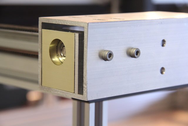
Belt Tensioners
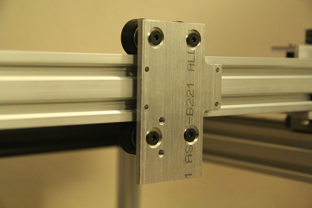
My best example of Designing for Calibration came out in the y-axis belt tensioners. (I’m really happy with how well these turned out.) The Y-axis is driven with 2 open belts that are cut to length and then clamped to the moving axis with clamping plates. Since these are timing belts, the entire length of the belt can only be shortened/lengthened in discrete steps, about one belt tooth long. I could calculate the correct number of teeth needed to fix the belt in its final location on the gantry with the proper tension, but there are wayy too many other parts that will also need to measured and cut to exact lengths for the belt to truly fit correctly. Furthermore, the belt length might change ever-so-slightly with age, and my entire design is hosed if it can’t accommodate for a belt that becomes marginally looser over time. Ok, it’s “design-for-calibration” to the rescue here!
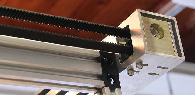
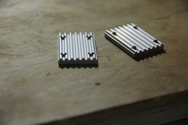
Pulleys are installed in their own pulley blocks, but their final placement can be slid back and forth to accommodate for both the actual number of belt teeth and the amount of tension that I want to tighten them to. On these pulley blocks, I’ve affixed an aluminum plate to the back with threaded holes where I can install screws. Adjusting the tension is just a matter of rotating these screws from the back.
Now that my machine can be calibrated, it’s starting to stray out of the world of hacks and into the world of engineering design! I’m pretty jazzed. Don’t worry, though. There are plenty of hot-fix and hot-glue moments up ahead that’ll keep this baby from being mass-produced and sold to the masses.
the Grammar of the Nuts and Bolts
Sourcing Materials
For side projects, I usually have the “get it working; then, redo it until satisfied” approach. For that reason, I wont hesitate to snag the off-the-shelf part to make the journey a few hours shorter. Misumi belt clamps and Open-Builds v-groove wheels were some of my favorites:
Vendors for Obscure Items
- Honeycomb Flooring: HoneyCommCore or McMaster-Carr
- Budget Linear Slides: Aliexpress
- Plastic Panels cut to length: Tap Plastics
- Aluminum Extrusions: OpenBuildsPartStore
- Optics, Laser Tube, Water Chiller, Power Supply: LightObject
- Fume Extraction HTGSupply
- Stepper Motor Controllers GeckoDrive
The Occasional Tape and Glue
I really try to stray away from both of these “tacky solutions,” but there are a few occasions where it just makes sense.
VHB Tape
The laser cutter lid is a giant slab of quarter-inch acrylic. (FYI: Acrylic is opaque to the 10600[nm] wavelength, but everyone still gets goggles when it’s running.) To fixture that slab to an aluminum frame, I (winces) taped it down with a knockoff brand of VHB Tape. Scary stuff that VHB Tape! It’s 8 mils thick, double sided, and exceptionally good at sticking metals and plastics together, permanently. The strength comes from an acrylic bonding compound in the adhesive that cures to full strength in 24 hours. Once it’s on… well, yeah, it’s not coming off… at least not without lots of IPA to weaken the adhesive. In the real world, some folks use VHB variants to fixture metal stock for machining. Other folks actually use it in products for permanent housings that aren’t meant to be re-opened.
Hot Glue
To install the limit switches, I was originally planning for a few 3D-printed fixtures. In my excitement/haste, hot glue ended up being just as effective for a temporary solution, though!
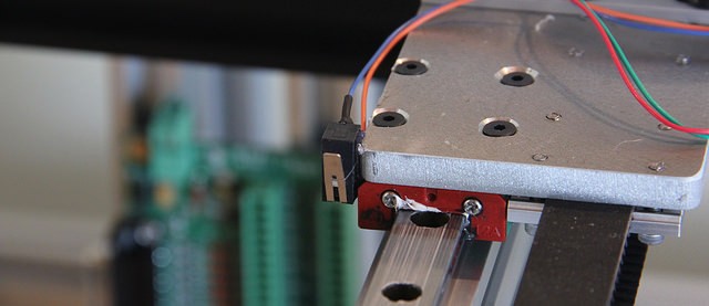
Luckily, I’m building this device for myself, not a host of benevolent customers, so I don’t feel too guilty about this temporary shortcut.
Breathing Freely
Eager as I was to kick of a laser cutter build, I’ve been putting it off for months because I couldn’t find a great solution for fume extraction. CO2 laser cutters kick out heaps of messy fumes since, in many cases, the laser is vaporizing the material it’s cutting. Some materials are on my cutting “blacklist” since they create toxic fumes. Those I’ll never cut. (PVC, I’m looking at you.) The majority of the others will create less-noxious fumes as well as fine particulates that still aren’t a great for breathing. Nearly all professional systems will recommend some form of fume extraction, and they’re usually kind enough to provide you with an exhaust hose by which you can redirect the smell to your least favorite neighbor. On my end, my neighbors seem like nice folks, so I couldn’t live with the thought of smelling up our backyards with small particulates. To remedy the issue, a friend-of-a-friend pointed me towards a few suppliers for the indoor plant growing community. It turns out that they also sell fantastic budget carbon filters and can fans.
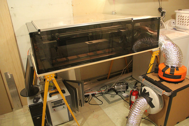
Armed with two fans and a carbon filter, fumes now get redirected out the enclosure, through a carbon filter, and finally outside. Best of all–the smell has almost completely vanished. (There’s still bad whiff from opening the lid, but that’s expected.)
Tuning
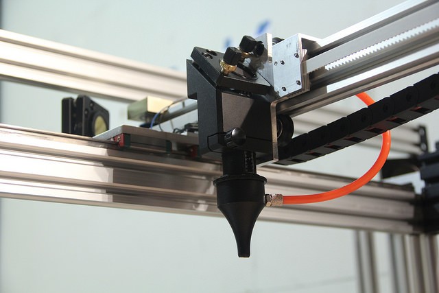
Optics Alignment
Most CO2 laser cutters use a “Flying Optics” setup to move the focused laser over the material. This setup has massive advantages in that the tool that’s actually doing the cutting (the laser tube) is stationary, and the end effector that’s moving the beam around isn’t experiencing any load while it cuts! The benefit? We can build the gantry with low-power, open-loop stepper motors that have just enough torque to move around a few mirrors. The downside is that we need to align those mirrors such that our laser can still reach the output lens in all sections of our material bed.
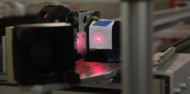
Line up a few mirrors with an invisible beam that burns everything in its path–how hard can it be? Fortunately, forums and youtubers worldwide have kindly documented the procedure. First off, I needed a ballpark figure of where the laser was landing, so I blasted a few pieces of paper to mark the original location. From there, I dropped in a “guide laser” and centered it over my burn marks such that the red beam, more-or-less, followed the path of the original laser.
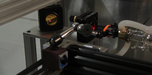
From there, I worked my way from the laser tube to each mirror, tweaking each stage until the beam remained in the same spot of the laser nozzle in all four corners of the gantry. Phew! That’s a lot less smelly than repeatedly burning holes in tape with the actual laser.
Laser Alignment Links
- Light Object Forums Illustrated Guide
- Just-Add-Sharks Tuning Knobs Explanation
- Stephen Hobley’s Guide Laser Setup
The Software Pipeline
Before I started this project, I made sure that I could string together enough open source software to go from DXF to STEP-and-DIRection pulses for the motor controllers. Here’s a quick overview of what I’m using.
File Exporter: DXF-to-GCode
Solidworks, Autodesk, and a few other Engineering CAD programs can export a 2D vector graphic in DXF format of the shape that we’d like to cut. From there, we still need to convert this illustration to the corresponding GCode. To accomplish that job, I opted for DXF-to-GCode, an open-source converter with a built in GUI. I could gush about this piece of software for hours. Originally intended for milling machines, it enables you to control the order of the cuts and exports a file that renders GCode with the corrected path to offset for the width of the tool. My “tool” (the laser focal point), is small, but accounting for its width is the difference between parts that fit snugly together and parts that dont slip together at all. Luckily, since it’s open-source, I was able to tweak it to get it to export the custom GCode that my interpretter demanded to drive the laser. Feel free to snag the tweaked version here.
GCode Interpreter: LinuxCNC
While there are plenty of 3D printer gcode interpreters, LinuxCNC is by far the most mature. With tunable backlash compensation, machine types, and a built-in gcode visualizer, it had all the standard features I’d expect to drive an X-Y table.
Furthermore, a few folks have actually enhanced the original software package with a custom addition that enables pulsing the laser as a function of position (sometime referred to PPI or PPMM control). PPI control pulses the laser as a function of position. What this means is that the laser cutter is actually “perforating” your material as it cuts.
This scheme for cutting seems a bit bizarre, so why do it, you might ask? It turns out that CO2 lasers peak in their power output about 1-2 milliseconds after they’re powered on. This peak dies a few milliseconds afterwards down to a steady-state value that’s below the peak. By repeatedly powering on the laser, or “pulsing it,” we can continue to produce this peak, effectively maximizing the power output of the laser over time. The downside is that we need a slightly more intelligent controller to pulse the laser as a function of position, but, by the kindness of the folks behind the 2x_laser, we get this feature for free!
The downside to LinuxCNC? LinuxCNC is a real-time Linux Distribution, so I needed a completely separate (refurbished) computer to drive it, rather than just a simple controller and a usb connection to an existing computer.
The Takeaway
Back in college, I dreamed about cutting everything from composite costumes to modular robotics with my own laser cutter. Time flew. Reality settled in. Now, almost three years later, I set aside many nights over the last six months to make it happen. Three iterations later, I’m just about ready to sign off on this fellow. This project has been a beloved exercise in CAD, machining, and software, all in efforts to assemble a pipeline from CAD to cuts. Nessie is ready to make some beautiful pieces come to life–I’m really jazzed!
Extra Pics and More
- The Flickr Build Log
- From Hackaday: The Wonderful Scent of Etching Pi on Pie for Pi Day
- From Hackaday: Tales of Garage Design: Achieving Precision from Imprecise Parts