GameCube Robot
a differential drive train packed into a classic console

Update:
Building instructions for version 2 can be found online at instructables and can be built without specialized equipment (i.e: a machine shop).
Introduction
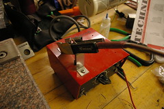
With yet another generation of game consoles on the horzion, what on earth will we do with all of our previous consoles? Now backlogged by two generations, the good ol’ Nintendo Gamecube sits patiently in many closets. I decided that it deserved some fresh air, so I took mine apart and turned it into a robot.
Lacking artificial intelligence of any kind, Gamecube-Bot is actually slightly more of an rc toy than a robot in its current state. However, with its differential drivetrain and the ease-of-reproducability added in with version 2, it’s just begging to be loaded down with sensors for multi-robot research problems.
The Design
Design a high-end research-worthy robot platform on-the-cheap? Challenge accepted. As many of us bot-designers over at Harvey Mudd College are learning, designing a drive train transmission takes time. Why? For us, our biggest hump was choosing the gears needed for an acceptable gear ratio. With brushless motors revving up to 10000[rpm], a transmission is vital to slow down that motor to an acceptable driving speed.
A Servo Replacement Gear Transmission (SRGT)
Choosing each gear separately from a supplier like McMaster-Carr or SDP-SI can send us digging deep into our wallets. The solution? Find an already-existing set of gears. In our case, a few of us have found that the HS-815/805BB servo replacement gears work shockingly well as a full transmission for 8-to-12[lb] differential-drive bots. (I owe this trick to JB at the Secret Underwater Base / Machine Shop who gave it a shot first and sent me the gear CAD files!)
This is my first shot at seriously working with gears, apart from the classic LEGOs of my past. The main principles are like so:
- Gears of identical diametrical pitch can mesh together
- Gear ratios are given by the ratio of teeth between the driving and driven gears
- Gears mesh by mating their pitch circles tangent to each other. (Plus a wee-bit more space for added backlash)
- Common gears generally have the worldwide-accepted pressure angle of 20 degrees
- Gears often come in standard Metric and US sizes. This is reflected in their pitch diameters
Gears mesh at the imaginary circles called their pitch circles, a property derived from tooth count and pitch.

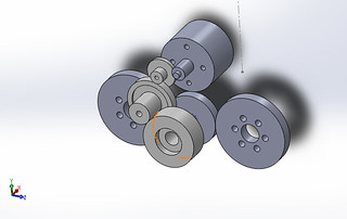
To make the gear stage shape a bit easier to design, I created a Solidworks Assembly using the gear files. I resized them to their pitch diameters and mated them tangent to each other so that I could freely position them while ensuring that each stage touched the next. (One quick note: I actually made the gears a wee-bit bigger than their pitch diameters, adding some backlash, to permit the gears to spin more smoothly.)
The pinion gear was a bit tricky to find. The servo replacement gears are metric, and finding metric pinion gears with the right inner shaft diameter became another hunting game that I didn’t want to play–especially if I happened to find the right gear from a limited line of one vendor’s rc car. Luckily, 64-pitch US gears can mate with their metric cousins of comparable pitch, a feature that expanded the gear-selection wide enough to find the right pinion gear.
Replacement Gear Mods
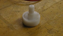
To prep the gears for continuous rotation, I had to clip off the limiting nylon tab feature on the output gear with the spline feature. Taking a great tip from JB once more, hot tweezers did the trick just fine.
Wheels and Hubs
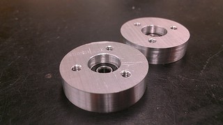
Once again, in choosing wheels, I opted not to rip wheels out of a vendor-specific rc car. Since LEGO wheels will (hopefully!) be around for years to come, I designed hubs around a set of four 56145 LEGO Technic wheels from my old sets. (There’s something special about using the old LEGO Mindstorms wheels on a bold new robot!) An aluminum hub and 32-pitch gear from servocity.com sandwich the wheel together (held together wih long 4-40 button-head screws).
Machining
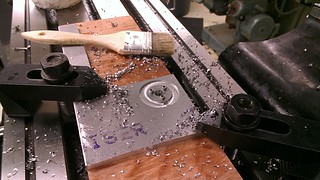
To ensure that the CAD files for the gear offsets would work, I made a quick test-plate with matching gear offets in the actual design. I was fortunate to catch small misalignment errors here, rather than in the actual part.
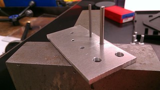
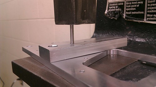
My first shot at press-fitting the servo gear shafts resulted in a crooked pin. Consequently, I made a second thicker plate with matching offsets but slip-fit holes to hold the pins as I press-fit them into the frame.
Following the first transmission’s completion and lubrication with silicone spray, we gave it a spin down in the shops.
Drive Train Initial Test
(That jiggly spacer was replaced!)
Implementation
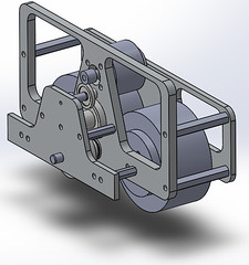
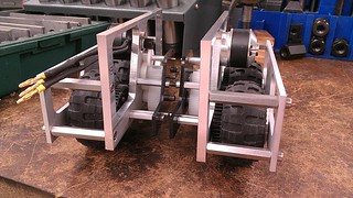
Once the two transmissions were created (correctly this time!), I zippy-tied them together with a steel plate from an old hard drive. (Ah, having a scrap pile is a lovely thing!) Following the crude assembly, we spun some initial outdoor tests:
Skeletal Drive Train Outdoor Testing
Fully-shelled Gamecube Living Room Test
Signal Mixing for Differential Drive Control
The differential drive train is driven with two brushless motors, one per side. Each of these brushless motors is driven by a brushless motor controller that accepts PWM input signals from the rc receiver. Since each motor is controlled by a separate channel, these channels must be mapped to a control-stick scheme that makes sense; otherwise, the controls are offset by 45-degrees, making the driving experience a bit strange. Rather than remapping the channel output signals with an embedded board like an Arduino, it’s much cheaper to place in a V-tail mixer cable between the two channels. (They’re only $3.) (The video above is actually before I snagged a mixer.)
Outlooks
I’m thrilled that the srg-transmission works so well, and I’d really encourage others to take the leap! With some more effort, I’m convinced that a cheaper laser-cuttable edition is on its way in the near future. For the budding Arduino hobbyist, this could be the beginning of an awesome new development platform with brushless motors. Alas, only time will tell.
Finally, now that I’ve got a hardware platform to work with outside the labs, I’d like to give some budget mouse odometry a shot to see how well I can get it to track it’s position for future state-estimation projects.
References
- Source Code and Original Documentation
- Side-By-Side image credit to Ben Chasnov
- The Flickr Picture Feed
- SDP/SI Notes on Metric Gears
- The Secret Underwater Base / Machine Shop, lair of the machining guru JB.
- Harvey Mudd College Combat Robot Club Facebook Page