Rotary Encoders
theory and implementation
Perhaps after controlling a few DC motors, you may be wondering if you can get a bit more
precision. For instance, what if I wanted my robot to drive forward exactly 10.0 [ft]?
With a typical DC motor, all we can really do is make a good guess. With encoders,
however, we can do better! We can introduce–feedback!
The General Theory
Today, we’ll be examining (two-channel) optical encoders in more detail, and I’ll
guide you through the process of decrypting their output signals. Encoders can
give us priceless information: they can tell us what angle the connected shaft is
oriented. From that info, we could backtrack angular velocity and acceleration!
But there’s a price. Unlike most other sensors, where we can just poll the sensor
at any time, we always have to keep track of the encoder to see if it’s changed angle.
Relative, rather than absolute values
Here’s a quick example on the difference between reading a typical sensor and reading an encoder. A simple light sensor responds by changing it’s resistance depending on how bright it is. No matter when we sample it, it will give us the light reading at the time of measurement. On the other hand, an encoder, just spits out two pulses every time it changes it’s angle by a small increment. In other words, to deduce our overall angle, we have to sit there and “babysit” the encoder, keeping track of every new pulse we see since we’ve started.
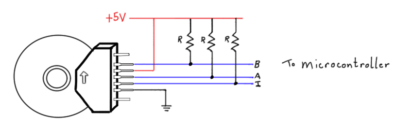
The Pinouts
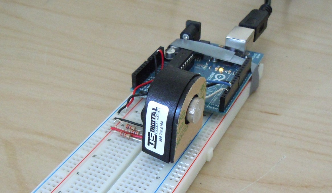
Let’s take a look at the guts of the two-channel optical encoder. Inside the encoder
is a small disk with tiny slits. This disk connects directly to your rotating shaft.
At the bottom of the encoder is a fixture that holds an LED and two light sensors that
connect to the encoder’s pinouts: channels A and B. The disk rotates through this
fixture freely, and every time a slit passes the light sensors, the light beams break,
and the voltage from these signals drop.
It turns out that the way these two light sensors are spaced apart inside the fixture produces a two very specific outputs. if we look at the signals produced from these two internal light-sensors as we rotate the disk, we’ll find that one waveform is halfway “out of phase” with the other. Here’s a quick pic:
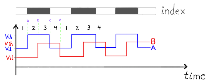
If we measure both channels at the same time, we can see four distinct transitions on the signals above.
               Channel A:                Channel B:
Case a:        Low-->High                Low
Case b:        High                      Low-->High
Case c:        High-->Low                Low
Case d:        Low                       High-->Low
In other words, there are really only 4 possible modes (or states!) that occur in a repeating pattern over and over. In the next section, we put all of these states into a finite state machine:
Decrypting the Output: a Finite State Machine
In the following finite state machine diagram, each state is represented by a circle, and the transitions in and out of that state are triggered by the what happens to channel A or B (printed above the arrow). This abstract FSM is exactly what we want to put into the software that decodes the signals. At this point, if you’re staring at a strange-looking FSM diagram and wondering how to code it up–Have no fear! Once we’ve created the FSM diagram, we’ve actually already laid out most of the code structure!
To decrypt and interpret our rotary encoder, we’ll be using an Arduino. On the software level, we’ll want to call on Interrupts, so that we can watch for changes from the encoder essentially at any time they might happen. Using an interrupt essentially means that the Arduino will stop whatever it was doing at the moment, handle a quick task to keep track of the encoder’s new angle, and then go back to whatever it was doing originally.
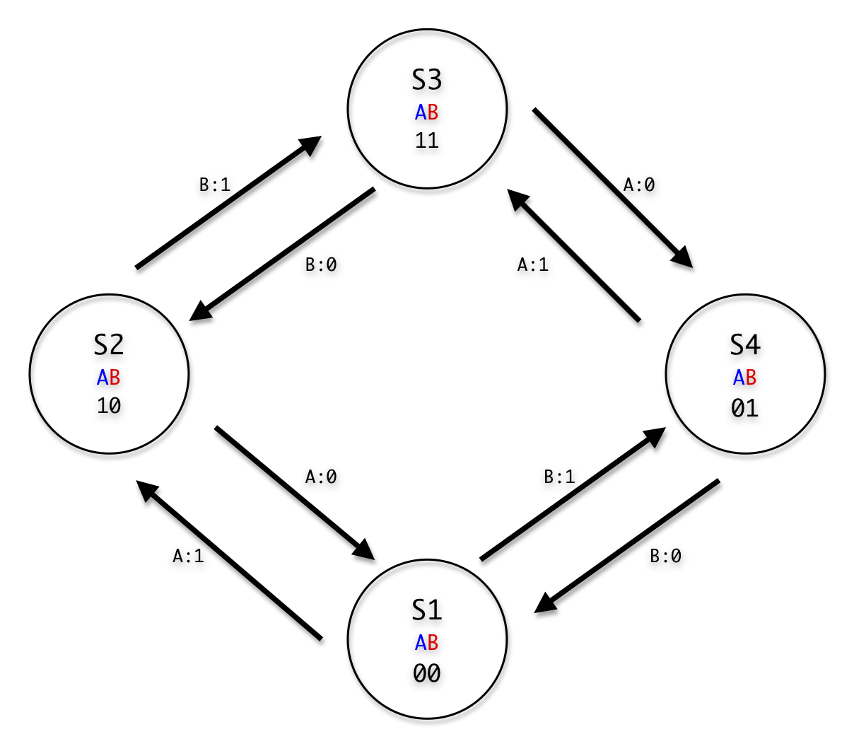
In the code below we do two simple things in each state:
1. We setup all the ways we can get out of that state for the next transition.
2. We increment (or decrement) the current index accordingly.
Reading on the EDGE: an unexpected resolution bump
For this demonstration, I used an encoder with 500 CPR (counts per revolution).
This CPR value tells us that there are 500 slits on the encoder’s internal disk.
However, since we’re monitoring the transition on the edges of the slit, we actually
get 2000 points of resolution from the encoder! Neat, huh? This is all thanks to
the fact that the Arduino has interrupts that respond to both types of signal
changes: a RISE and a FALL.
Resources
http://awtarlab3.engin.umich.edu/wiki/index.php/Arduino
http://abrobotics.tripod.com/Ebot/using_encoder.htm
http://arduino.cc/en/Reference/AttachInterrupt
http://www.engblaze.com/we-interrupt-this-program-to-bring-you-a-tutorial-on-arduino-interrupts/
Project Files
The full Source code can be downloaded from Github here. Enjoy!