2W Diode Laser Driver
Update:
The original schematic posted did not correctly charge the bootstrap. The revised verison (shown below) uses a different component (the LT1910) that fixes this problem.
As opposed to our classic LED, laser diodes are a bit trickier to setup. First, they’re a bit more sensitive to voltage spikes. A static discharge can render a pricey diode now a useless trinket to add to the pile of nice-looking paperweights. Next, the reverse voltage can be as little as a few volts, which means that plugging it into the system backwards can also fry it. Addiionally, laser diodes are heat-sensitive, and overheating them can also lead to their destruction.
A Note on Safety
Apart from the risks to the diode, the diode also poses a risk to the operator. In a matter of microseconds, a rogue beam can render one blind permanently.
With this precaution, if you pursue this avenue of working with lasers, keep the risks in mind, make yourself aware of them, and wear the right goggles. By the right goggles, I’m referring to goggles that sufficiently protect against the wavelength that you’re working with.

For this project, I’ve chosen goggles that are rated as OD6+ within the 445 [nm] range. The “OD” rating, refers to how many orders of magnitude by which the input laser power will be reduced before passing through the eyepiece. Thus, a 2[W] laser shining through a lense with an OD6 rating exits through the other end with 2 microwatts of power.
The Driver (Updated July 2014)

Power Output
In many cases, the LM117 seems to be the go-to solution for driving small laser diodes. After all, its datasheet lists a simple circuit for reconfiguring it as a constant current source. I wanted to find a solution that could handle just a bit more current without the added complexity of designing a constant current source from scratch. With a bit of online catalog hunting, I discovered the LM338, another adjustable voltage regulator that could source up to 5[A]. Like the LM117, the LM338 can also be
Diode Protection
Because the laser diode is vulnerable to voltage spikes, I’ve added two diodes to the output circuitry. The first is a zener diode, limiting the operating voltage of the diode to 4.6[v] and preventing voltage spikes in the forward direction. The second diode is a schottky diode, preventing voltage spikes in the reverse direction.
Adding an Enable
With the intent of turning on the laser with a microcontroller, I’ve added an enable with an n-channel mosfet. However, because the mosfet is above the load and because a microcontroller operating voltage is only a few volts, A high-side driver is needed to turn the mosfet fully on. With the IR2101, the voltage at the gate is ensured to be substantially above the voltage at the source. while the input voltage now needed to turn on the laser is within the range of 3.3[v] logic.
Simulation
In the first iteration, I went from breadboard to PCB without sufficient testing. The resulting circuit worked… sometimes. To prevent unpredictable behavior of the next iteration, I went back to the beginning and started with a mock-up simulation in LTSpice. Here I discovered a small voltage spike, and added an inductor at the end of the circuit to prevent the spike from destroying the diode. LTSpice doesn’t support generic components, so the resulting model was approximate, though it’s a good insight to potential drawbacks in the breadboard implementation.
Breadboarding
The LT1910’s datasheet remarks that a highly-capacitive load can false-trigger the chip’s internal comparator sensing the current load. The constant-current supply does just that, draining large currents on startup. Fortunately, a filtering method is provided in the datasheet.
An Etched PCB

In the spirit of making this project standalone and off the breadboard, I etched a double-sided pcb with copper(II) chloride (aka: cupric chloride). A surface mount header provides easy interconnectivity with a microcontroller an external power supply. Since the system only draws about 1[A], these header pins aren’t a bad choice for interconnectivity.
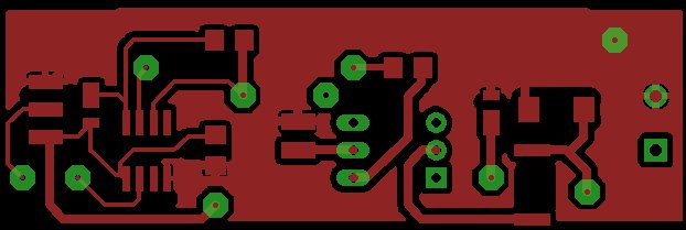
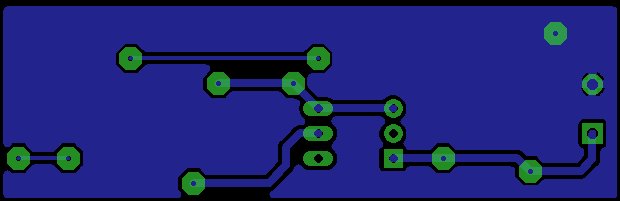
To cut out jumper wires entirely, I made two layers, and connected top and bottom with vias made by drilling holes and soldering snipped wire. For a DIY board, I’d recommend checking continuity as each via is created, since this is an easy spot for a cold solder joint.
Results
So far, the driver sources about 960[mA] and successfully drives a 2[W], 445 [nm] diode from ebay. As time goes on, I’ll be implementing a driver like this one in a paper laser cutter project hopefully later this year.