Modeling a crude model for many stock parts that already exist isn’t too bad. Features are usually either consistently in imperial or metric units, and a good set of calipers can reveal these numbers to us as we try to recreate the part in CAD. A few cuts, fillets, and extrudes later, and we might have the spitting image of the part we’re holding in our hands.
But what about when we’re modeling a creative project? More realistically, what if we’re modeling a part who’s exact shape is undetermined but still needs to conform to certain size constraints?
Enter parametric modeling.
When the relationships between features and other mating parts start to matter, it’s handy to plant down some reference sketches and start using variables to ensure that size relationships are respected while we explore small tweaks in the overall shape of the part we’re modeling. Better yet, it may even be handy to model many parts as one part with Solidworks’ multibody part feature.
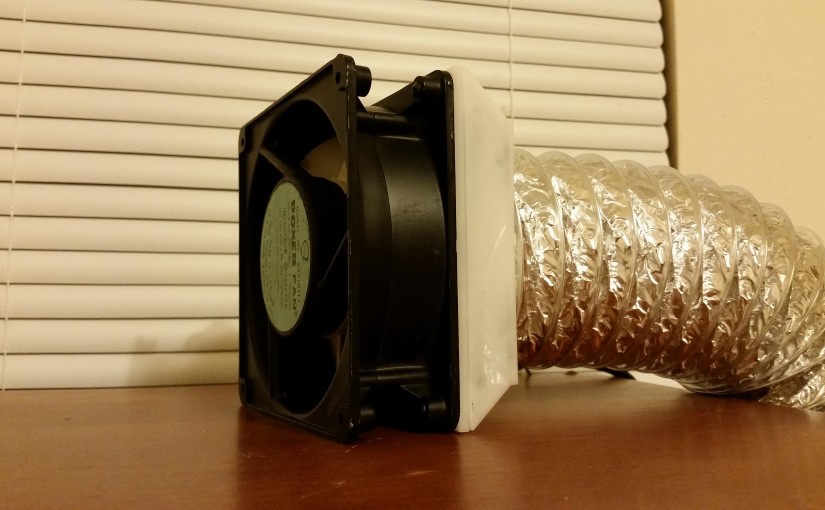
This past weekend, I thought I’d try to throw together a Soldering Fume Extractor for the garage bench with some cheap parts. I picked up a discarded 120 [V] AC server fan from an old surplus store and a 3-inch foil air duct from the local home-improvement shop. Alas, both parts didn’t just fit together…. Perfect–a chance to try out multibody parts in Solidworks!
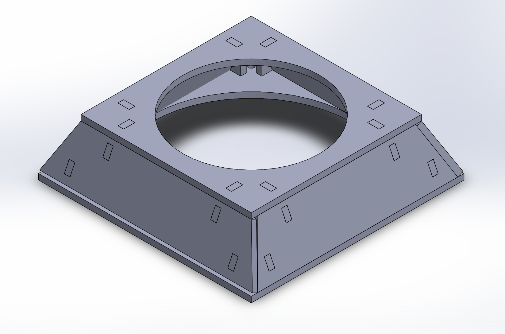
The image below is my airflow adaptor to convert the output of the fan to a surface that I could easily attach to the air duct. The design is intended for 1/8th-inch laser-cut Delrin, and the brackets are all press-fit (also Delrin). Unlike most of the other models I’ve made, this piece is just one Solidworks *.sldprt file! Separate pieces are separate bodies in a single “multibody-part.” The beauty of designing multiple bodies into one part is that we can easily accommodate the relationships between separate mating pieces that “puzzle-piece” together into one airflow adapter. Best of all, multibody-part design is a major time-saver! Since I didn’t have to create the six different pieces as separate Solidworks files, the CAD model only took about 2 hours to design!
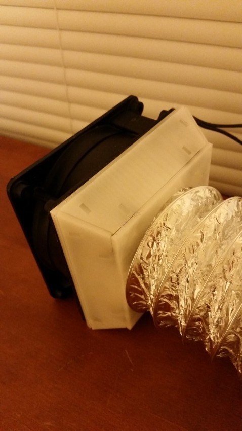
The final design is laser cut out of a sheet of 1/8th-inch Delrin. I wasn’t confident in the press-fit brackets, so I pasted some Sugru around each bracket’s edges. (Heads-up: most glues don’t adhere to Delrin at all. Even Sugru can be scratched off.) I also filled in the seams with Sugru to keep the fumes from escaping prematurely. The final result holds itself together quite nicely!
I’ve seen a few excellent “bathroom fan” implementations for fume-extractor builds. Bathroom fans are pretty cheap as-is, and they can move air around at a respectable 50(ish) [CFM]. That said, my surplus fan was only $12.50 and labeled as kicking out a whopping 85 [CFM]! If you’re interested in rigging an old server fan as a fume extractor, I’d highly recommend the “120-V-AC-Server-Fan” method. In case you’re a bit far from an electronic surplus store, I also discovered a similar fan at AllElectronics, although the CFM rating is a bit lower.
Not a bad weekend for about four hours of design-and-assembly and a resurrected piece of junk from the scrap heap!