Form1+ Test Transmission Results

(continued from part 1)

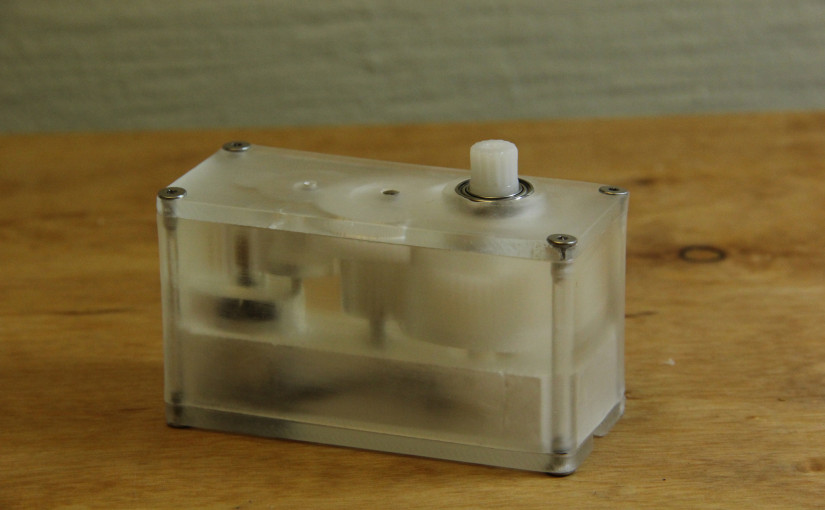
The results are in! I’m thrilled that the Form1+ was able to achieve tolerances tight enough to nail the spacing for 0.4-Module gearing.

The video below is just a brief back-and-forth test of the 60-watt motor.

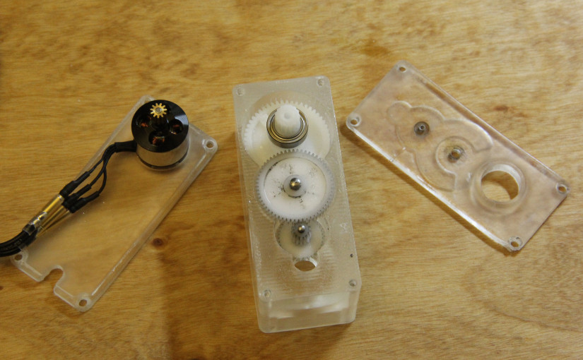
To get the transmission to run above, I didn’t need to do too many touch-ups, but here’s the breakdown of the adjustments I did make.

  • I lightly sanded the lid where the gears rub and added brass washers to each shaft on the other side of each gear.
  • The M2 dowel pin shaft slipped into it’s hole a bit too easily after post-curing the case. A dab of Loctite 409 resolved this problem pretty easily.
  • I sanded and polished the final pieces with 600 grit sandpaper (wet) and Novus Plastic Polish so that I could see through the case. With only 20 minutes of work, I was able to see through, but it’s not a glossy finish that I could achieve with more work.
  • I gave the gears a quick squirt of silicone spray before running them.
  • The holes on the CAD file were sized for threading with a tap, but I ended up screwing in the screws directly before post-curing the parts in the sun.

I actually really like that the prints are still somewhat flexible after printing. I may capitalize on this feature and push the dowel-pins into their holes and then post-cure the resin to its complete hardness.

A quick note about the sound:

At low speeds, the motors give off a very audible whine. This shriek is from the PWM frequency of the electronic speed controller, currently at 8 KHz. When the motor starts to spin, the temporary electromagnets from the commutation sequence need to attract the rotor magnets. When they don’t cleanly commutate at low speeds, the stator magnets and rotor electromagnets snap together, causing the motor to vibrate more audibly at the PWM frequency and giving off that nasty, 8 KHz whine. I wonder if other motor controllers can pulse past the audible range…. Nevertheless, compared to the last transmission I made with these gears, which didn’t have an enclosure, the new transmission is far quieter and much more tolerable indoors.

The full parts list and the STL files are available after the break:

Continue reading Form1+ Test Transmission Results

The Hackaday Prize 2015

Last year, Hackaday.io pulled both the projects and the engineer-by-night out of their garages and into broad daylight where all could see. As a community, these night-time-tinkerers refresh us with their new ideas as they use-and-abuse their tools to provide a great insight. This year, the Hackaday community encourages you to get out there once more as it launches The Hackaday Prize 2015.

Hopefully, if you’re out to save the world, you’re in luck! This year’s theme looks at the worlds problems and asks you to build something that turns around and takes a stab at solving them. So go out there: burn something–learn something! In the name of science (uh, safety first), let’s use what we have (and have yet to acquire) to build something awesome.

Form1+ Test Transmission Print

I’ve avoided 3D printing for as long as I can. Now that I’m away from a marvelous school machine shop, though, I thought I’d finally take the dive after some of the success that [JB] has been having with functional prints.

This project is a bit of an old hat. Since [JB] first pointed us to using servo replacement gears as mini-combat-robot transmissions, I’ve been dropping them into project after project whenever I need a little gear reduction. Compound gears–especially the kind that can take a bit of torque in small projects–are pretty annoying to source. This all-in-one set of servo replacement gears gives us a kit that works pretty well for many simple applications.

These replacement gears have a bit of magic “zen” in that the rest of the parts needed to work with them are all stock from McMaster-Carr. It just so happens that M2 and M3 dowel pins will slip-fit into the gear bores almost perfectly (the smaller bore needs to be hand-widened with a 2mm drill bit), and two metric bearings on the output gear enable smooth and high-speed output via the spline.

(For more details on actually doing something with that spline, see [JB’s] spline adapter post.)

Continue reading Form1+ Test Transmission Print

Timers, Encoders, Rollover, and the Magic of Two’s Complement (pt 1 of 2)

In the Arduino world, delay functions are convenient.

void loop()
{
    doSomeCoolStuff();
    delay(1000);
}

Unfortunately, they’re also impractical.

Let’s say we tried to doSomeCoolStuff once per second. The code snippet above doesn’t actually behave that way because it ignores how much time the doSomeCoolStuff function call takes to return. If doSomeCoolStuff takes 15 ms, then the loop actually runs at a rate of 1.015 ms, not 1.000 ms.

One solution is to use a timer. Arduino’s hardware-abstraction layer actually makes using timers strikingly easy. milis and micros return the respective milliseconds and microseconds since the program first elapsed. Now, provided that doSomeCoolStuff() takes less than one second to complete, we might try writing the code like this:

const int LOOP_TIME = 1000;
unsigned long lastTime = 0;

void loop()
{
    unsigned long elapsedTime = millis() - lastTime;
    if (elapsedTime == LOOP_TIME)
    {
        lastTime = millis();
        doSomeCoolstuff();
    }
}

There are two subtleties here, though, but first let’s see what the code does.  Since loop repeats itself as long as the Arduino is powered, elapsedTime continues to get reassigned and checked against LOOP_TIME. If they’re equal, a new lastTime gets assigned and doSomeCoolStuff happens.

The first problem here is that code is rarely this simple. Let’s say we call some other function in the loop:

const int LOOP_TIME = 1000;
unsigned long lastTime = 0;

void loop()
{
    unsigned long elapsedTime = millis() - lastTime;
    if (elapsedTime == LOOP_TIME)
    {
        lastTime = millis();
        doSomeCoolstuff();
    }
    doSomeOtherStuff();
}

In this case, we’re also calling doSomeOtherStuff at every single loop iteration. I haven’t timed how long doSomeOtherStuff will take, but it might fall just outside the millisecond range such that 1001 or more milliseconds have elapsed before the if case is queried. If such a case happens, then doSomeCoolStuff will miss its chance to run and elapsedTime will increase until it rolls over, a very long time from now.

The fix? Check against an inequality:

    if (elapsedTime >= LOOP_TIME)

Now, even if 1001 seconds elapse, doSomeOtherStuff will indeed trigger.

Ok, now for the last point worth mentioning: can we guarantee that this line works in all edge cases? i.e: will elapsedTime always return a number between 0 and LOOP_TIME, or will it return a huge number in some weird overflow-error case?

    unsigned long elapsedTime = millis() - lastTime;

The short answer: actually yes! The longer answer is in that the binary number two’s complement representation actually handles this very gracefully.

More on that in part 2….


Brave New World

On the quest to build my next robot, no one mentioned that I was going to have some metastability issues, noisy data, and undefined references to main(). (Look, bub, I just signed up for the robots–what’s with all this extra stuff I ended up learning along the way?)

To fellow tinkers, engineers, and DIY-enthusiasts, this brain dump of notes and tricks are for you. May they spare you many headaches in your future endeavors.

Cheers!