Sketch-Driven CAD and a Fume-Extractor

Modeling a crude model for many stock parts that already exist isn’t too bad. Features are usually either consistently in imperial or metric units, and a good set of calipers can reveal these numbers to us as we try to recreate the part in CAD. A few cuts, fillets, and extrudes later, and we might have the spitting image of the part we’re holding in our hands.

But what about when we’re modeling a creative project? More realistically, what if we’re modeling a part who’s exact shape is undetermined but still needs to conform to certain size constraints?

Enter parametric modeling.

When the relationships between features and other mating parts start to matter, it’s handy to plant down some reference sketches and start using variables to ensure that size relationships are respected while we explore small tweaks in the overall shape of the part we’re modeling. Better yet, it may even be handy to model many parts as one part with Solidworks’ multibody part feature.

This past weekend, I thought I’d try to throw together a Soldering Fume Extractor for the garage bench with some cheap parts. I picked up a discarded 120 [V] AC server fan from an old surplus store and a 3-inch foil air duct from the local home-improvement shop. Alas, both parts didn’t just fit together…. Perfect–a chance to try out multibody parts in Solidworks!

multibody-solder-fan

The image below is my airflow adaptor to convert the output of the fan to a surface that I could easily attach to the air duct. The design is intended for 1/8th-inch laser-cut Delrin, and the brackets are all press-fit (also Delrin). Unlike most of the other models I’ve made, this piece is just one Solidworks *.sldprt file! Separate pieces are separate bodies in a single “multibody-part.” The beauty of designing multiple bodies into one part is that we can easily accommodate the relationships between separate mating pieces that “puzzle-piece” together into one airflow adapter. Best of all, multibody-part design is a major time-saver! Since I didn’t have to create the six different pieces as separate Solidworks files, the CAD model only took about 2 hours to design!

solder_fan_back

The final design is laser cut out of a sheet of 1/8th-inch Delrin. I wasn’t confident in the press-fit brackets, so I pasted some Sugru around each bracket’s edges. (Heads-up: most glues don’t adhere to Delrin at all. Even Sugru can be scratched off.) I also filled in the seams with Sugru to keep the fumes from escaping prematurely. The final result holds itself together quite nicely!

I’ve seen a few excellent “bathroom fan” implementations for fume-extractor builds. Bathroom fans are pretty cheap as-is, and they can move air around at a respectable 50(ish) [CFM].  That said, my surplus fan was only $12.50 and labeled as kicking out a whopping 85 [CFM]! If you’re interested in rigging an old server fan as a fume extractor, I’d highly recommend the “120-V-AC-Server-Fan” method. In case you’re a bit far from an electronic surplus store, I also discovered a similar fan at AllElectronics, although the CFM rating is a bit lower.

Not a bad weekend for about four hours of design-and-assembly and a resurrected piece of junk from the scrap heap!


Arduino Clones 101: Essential Schematic Features

Making our own Arduino Clone is actually pretty straightforward! We just need to include a few necessary features on the schematic and PCB Layout. Below, I’ve listed a collection of all the schematic features that need to be included to get a successful Arduino Clone up-and-running.

The Clock Source

clock_sourceHere’s the heartbeat of our system, the clock source. This design has a 16 [MHz] crystal oscillator, but frequencies up to 20 [MHz] are fair game for an atmega328p. (I’d recommend sticking with 8 or 16 [MHz], though, such that all of the delay functions in the Arduino IDE work as expected.) The clock source here requires two capacitors at 8 [pF] each. More details on what cap values to choose are listed here.

You can actually omit the external oscillator from the design entirely if you choose to do so, since the atmega328p (and most other AVR chips) have a built-in internal oscillator that can be used as a clock source.  Regardless of whether or not you omit an external clock, you’ll still need to configure the fuse bits such that the microcontroller recognizes and uses the correct clock configuration that you’ve chosen.

The Bypass Caps

bypass_capsIf you’ve stared at schematics often in the past, it’s not uncommon to see these “rogue capacitors” that seem to be just “dangling there” without any explanation. It turns out that these capacitors are vital for correct board behavior. I don’t have a set of equations for this one, but in a nutshell, these caps dissipate small voltage fluctuations on the input power supply, ensuring that the microcontroller has a clean, “noise-free” power source.  On the PCB layout, place these capacitors (0.1 [uF]) physically as close as possible to each of the micocontroller’s VCC pins. (Heads up: we’re only dealing with a 16 [MHz] system here, so we don’t need to be too terribly scientific about the equations behind this governing proper noise dissipation.)

The Programming Header

programming_headerUnless your chip is pre-programmed, any Arduino clone needs a way to upload the program. There are three options here.

The first option is to add a 6-pin programming header through which you can connect an AVR In-System-Programmer (ISP). The shape of this connector on the PCB is up to you. You’ll just need to make whatever adapter cable needed such that the other end plugs into an ISP. Here’s a picture of my tiny 6-pin programming header on a SMD Arduino clone.

isp_header


My configuration here has a voltage supply input on the programming header, but if your PCB is powered elsewhere while programming, this Vcc pin may be omitted. It’s also good practice to put a pullup resistor (~10[K] is fine) on the RESET line to prevent accidental reset from noise on that pin.

The second and third option is serial programming, enabling you to upload codeM through the TX and RX pins. The catch is that you’ll need a bootloader, a small snippet of code already living on the chip, that essentially reroutes the incoming serial data into program memory. Depending on your setup, you may also need a method of resetting the board and putting it into “programming mode.”

While this method requires only two(ish) pins (TX and RX… plus RESET, GND, and maybe VCC), you’ll still need a way of configuring the fuse bits and uploading the bootloader. If a bootloader is not yet uploaded to the chip, then only the ISP method can be used for programming. Many companies pre-program the chip with the bootloader directly before they place it on the PCB by means of a ZIF socket. This method is convenient for consumers in that you don’t have to buy an ISP (~$15) before you can start uploading code. The downfall is that this method is a bit more difficult for consumers to achieve since they need their atmega328p chips to already have the bootloader flashed and fuse bits set before they install it on the pcb. (If you go with this method, you can actually buy chips with the bootloader pre-flashed.) For this reason, I prefer programming via the first method, although I did need to pick up that $15 programmer.

The AVCC and AREF Pins

avcc_and_arefAVCC and AREF are the analog input voltage and external analog reference pins respectively. If you aren’t measuring analog signals with the onboard Analog-to-Digital Converter (ADC), you’ll need to connect AVCC to VCC, as I did above. If you are using the ADC, you’ll need to connect VCC to AVCC with a low-pass filter on AVCC. Folks on the forums suggest just a 0.1 [uF] capacitor from AVCC to GND.

the AREF pin is for providing an external analog reference for measuring analog signals. (This method must be enabled in software and defaults to using the internal reference.) My circuit above didn’t use the external analog reference, so the AREF pin could’ve been left floating. If you do use the AREF pin, you’ll want to create a reference voltage value on that pin by means of a voltage divider or some other method.


That’s about it! Make sure your board has a source of input power that falls below the maximum operating voltage (+6[V]), and you should be good to go!

Cheers–and best-of-luck making your own clones!

Arduino Clones 101: Fuse Bits

The Arduino toolchain does a wonderful job of hiding away unnecessary complexity that would otherwise prevent us from building up projects quickly. The compilation procedure with avr-g++, the uploading process with an ISP (in-system programmer), and the pre-configuration of the chip via its fuse bits are all hidden parts of this process. But what happens when you need to “go off the deep end” and build an Arduino-compatible circuit board from scratch? In these cases we need to dig down to the level of embedded systems engineers and understand how things work at the low level so that we can put together a working system.

In this post, I thought I’d get started introducing the Arduino toolchain and then drop down a few notes about the fuse bits.

What is AVR?

AVR refers to an entire family of 8-bit (and some 32-bit) microcontrollers produced by Atmel. Within this family is a collection of microcontrollers (let’s call ’em chips), like the

  • atmega328p
  • atmega32u4
  • attiny85
  • attiny2313

and many more….

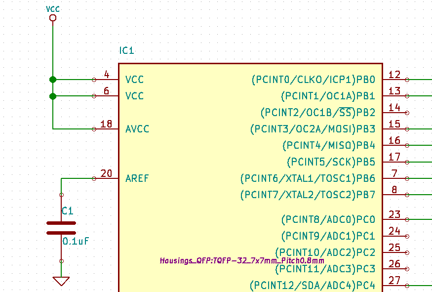
Some of  these chips we may have even been inadvertently working with all-along without even realizing it. For instance, the atmega328p is the microcontroller on the Arduino Uno. The atmega32u4 is the main chip on the Arduino Leonardo and the Teensy 2.0. These chips are the “main brains” on the development boards. Everything else on their respective boards is mostly additional circuitry that enables easy access to the pins and programming over USB.

What’s a Toolchain?

A software “toolchain” refers to a collection of software “tools” that, together, allow you to take C or C++ source code, turn it into an executable file that the microcontroller can understand, and upload it to the microcontroller’s onboard memory so that the microcontroller can run our program. In the case of Arduino, the toolchain is “all the complicated things that happen under the hood” when you press the upload button on the Arduino IDE up until our code starts running on the Arduino board.

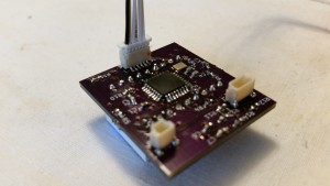
For slightly longer-term original projects where we want to spin our own printed circuit board (PCB) populated with the atmega328p, in many cases it still makes sense to use many of the tools provided to us by the Arduino IDE. My reasoning for this judgement call is that I’d prefer not to write my own toolchain just to upload code to an Arduino board. In this sense, I’d like to program this custom Arduino-compatible PCB with code written in Arduino and compiled with the Arduino-provided toolchain.

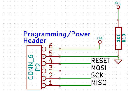
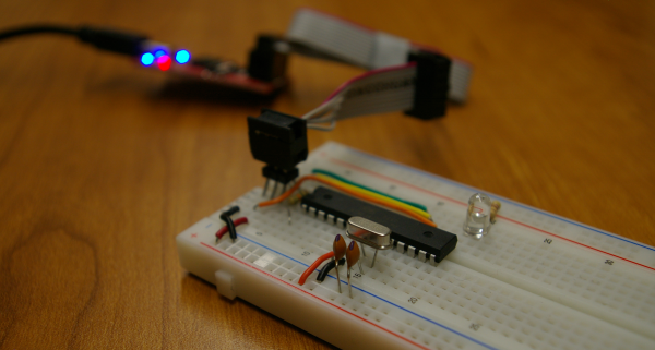
Before we can take a home-made Arduino board and start uploading code to it through the same toolchain, though, we need to do some pre-configuration. First, we need to design and fab our original PCB that enables programming via the In-System-Programmer (ISP) pins on the chip. (I’ll cover how to design an Arduino-compatible PCB in another post.) Next, we need to properly configure the fuse bits.

What are these Fuse Bits and why do they matter?

Fuse bits are a concept hidden to us if we’re programming Arduino Boards through the IDE. If we’re making our own Arduino-compatible PCB, though, we need to know what they are and how they affect our board.

Fuse bits refer to programmable settings for the microcontroller that tell it information about its hardware configuration. While they’re not one-time-programmable it is possible to (more-or-less) brick your setup if you upload the wrong fuse bits. Put another way, since these fuse bits tell the microcontroller important things such as: “what is my clock source?” and “should I disable reprogramming?”–it is possible to tell the microcontroller that it’s configured in a way that doesn’t match its actual configuration, in which case it may or may not listen to you.

Rest assured, there are calculators, forums, and blog posts that can give us an idea of what fuse bits we want to set before we actually write them over.

Which fuse bits do I set?

Which fuse bits you’ll want to set depend on your configuration. These fuse bits give the chip information as to

  • what clock source
  • disable programming
  • enable/disable clock prescaling for a slower processor speed
  • enable/disable brownout detection to reset the device below certain input voltage supply thresholds
  • set the starting address of program memory.

Which features to enable/disable are up to you and your configuration. Here’s some general guidelines:

  • Disable brown-out detection unless you really want to reset your circuit below certain voltage thresholds.
  • Keep the starting address of program memory at the default value.
  • Enable programming (otherwise you wont be able to program the chip after setting these fuse bits.)
  • Enable/Disable clock prescaling as you see fit. I generally put an external oscillator on my boards and disable prescaling unless I need to save power.
  • Choose the clock source that you’re actually using, and give it 65 [ms] delay time unless you can be sure that the oscillator is stable and ready before that window when the system first boots up.

It’s worth double-checking that (a) programming is enabled and (b) the correct clock source is selected before writing over the fuse bits. If not, you may not be able to communicate with the chip and render it “unprogrammable” unless you change the current configuration to whatever you set it to via the most recent fuse bit settings.

Writing over the fuse bits

Before going any further, make sure you’ve got avrdude, the flash utility, installed. Luckily, if the Arduino IDE is installed, then you get avrdude with it for free. I’m using the command line on Linux for this one. (You can do this on Mac and Windows, also.) It’s a three-line incantation, one for each group of fuse bits. Assuming our desired lfuse, hfuse, and efuse are 0xe2, 0xd9, and 0xff respectively, our command-line input would look like this:

avrdude -c usbtiny -p atmega328p -U lfuse:w:0xe2:m
avrdude -c usbtiny -p atmega328p -U hfuse:w:0xd9:m
avrdude -c usbtiny -p atmega328p  -U efuse:w:0xff:m

As each line is written, you’ll get a verification from avrdude. If you get something that says rc=-1, then avrdude can’t connect to your board for some reason. Either the power isn’t connected, the fuse bits are misconfigured to begin with, or there’s something wrong with the pcb design.

Keep in mind that these fuse bits are specific to the microcontroller. (i.e: An atmega32u4, the chip one on the Leonardo, will have different fuse bits from an atmega328p, the chip on the Uno.)

Atmega328p with Internal Oscillator:

For an 8-bit Arduino Clone using its internal oscillator, instead of a crystal (or external clock reference), the fuse bits are likely:

  • lfuse: 0xe2
  • hfuse: 0xd9
  • efuse: 0xff

Specifically, the settings are:

  • internal oscillator as clock source with 65 [ms] startup delay. (more info on the startup delay)
  • no clock division
  • default boot starting address
  • enable programming over SPI
  • disable brown-out detection

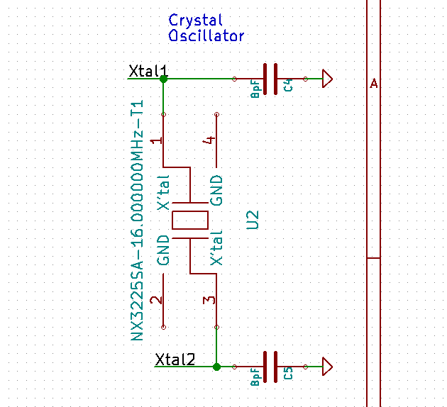
Atmega328p with External Crystal Oscillator:

For an 8-bit Arduino Clone using its internal oscillator, instead of a crystal (or external clock reference), the fuse bits are likely:

  • lfuse: 0xff
  • hfuse: 0xd9
  • efuse: 0xff

Specifically, the settings are:

  • external crystal oscillator as clock source with 65 [ms] startup delay (more info on the startup delay)
  • no clock division
  • default boot starting address
  • enable programming over SPI
  • disable brown-out detection


If you have need for brown-out detection, or any of the other settings for that matter, I’d recommend the AVR Fuse Calculator.