Making our own Arduino Clone is actually pretty straightforward! We just need to include a few necessary features on the schematic and PCB Layout. Below, I’ve listed a collection of all the schematic features that need to be included to get a successful Arduino Clone up-and-running.
The Clock Source
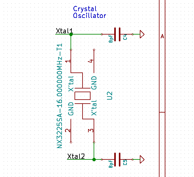 Here’s the heartbeat of our system, the clock source. This design has a 16 [MHz] crystal oscillator, but frequencies up to 20 [MHz] are fair game for an atmega328p. (I’d recommend sticking with 8 or 16 [MHz], though, such that all of the delay functions in the Arduino IDE work as expected.) The clock source here requires two capacitors at 8 [pF] each. More details on what cap values to choose are listed here.
You can actually omit the external oscillator from the design entirely if you choose to do so, since the atmega328p (and most other AVR chips) have a built-in internal oscillator that can be used as a clock source. Regardless of whether or not you omit an external clock, you’ll still need to configure the fuse bits such that the microcontroller recognizes and uses the correct clock configuration that you’ve chosen.
The Bypass Caps
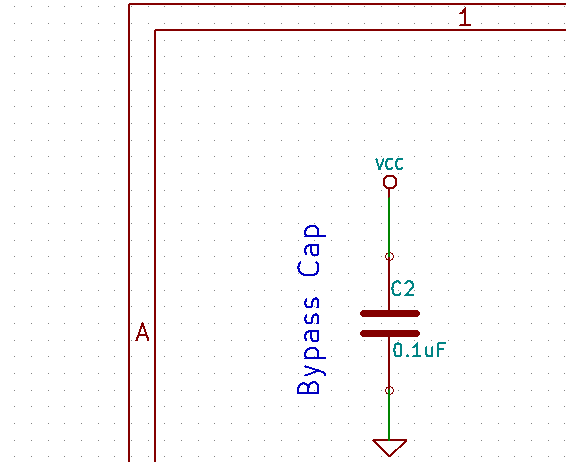 If you’ve stared at schematics often in the past, it’s not uncommon to see these “rogue capacitors” that seem to be just “dangling there” without any explanation. It turns out that these capacitors are vital for correct board behavior. I don’t have a set of equations for this one, but in a nutshell, these caps dissipate small voltage fluctuations on the input power supply, ensuring that the microcontroller has a clean, “noise-free” power source. On the PCB layout, place these capacitors (0.1 [uF]) physically as close as possible to each of the micocontroller’s VCC pins. (Heads up: we’re only dealing with a 16 [MHz] system here, so we don’t need to be too terribly scientific about the equations behind this governing proper noise dissipation.)
The Programming Header
 Unless your chip is pre-programmed, any Arduino clone needs a way to upload the program. There are three options here.
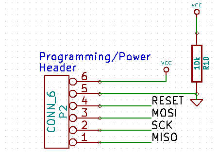
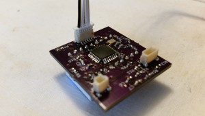
The first option is to add a 6-pin programming header through which you can connect an AVR In-System-Programmer (ISP). The shape of this connector on the PCB is up to you. You’ll just need to make whatever adapter cable needed such that the other end plugs into an ISP. Here’s a picture of my tiny 6-pin programming header on a SMD Arduino clone.
My configuration here has a voltage supply input on the programming header, but if your PCB is powered elsewhere while programming, this Vcc pin may be omitted. It’s also good practice to put a pullup resistor (~10[K] is fine) on the RESET line to prevent accidental reset from noise on that pin.
The second and third option is serial programming, enabling you to upload codeM through the TX and RX pins. The catch is that you’ll need a bootloader, a small snippet of code already living on the chip, that essentially reroutes the incoming serial data into program memory. Depending on your setup, you may also need a method of resetting the board and putting it into “programming mode.”
While this method requires only two(ish) pins (TX and RX… plus RESET, GND, and maybe VCC), you’ll still need a way of configuring the fuse bits and uploading the bootloader. If a bootloader is not yet uploaded to the chip, then only the ISP method can be used for programming. Many companies pre-program the chip with the bootloader directly before they place it on the PCB by means of a ZIF socket. This method is convenient for consumers in that you don’t have to buy an ISP (~$15) before you can start uploading code. The downfall is that this method is a bit more difficult for consumers to achieve since they need their atmega328p chips to already have the bootloader flashed and fuse bits set before they install it on the pcb. (If you go with this method, you can actually buy chips with the bootloader pre-flashed.) For this reason, I prefer programming via the first method, although I did need to pick up that $15 programmer.
The AVCC and AREF Pins
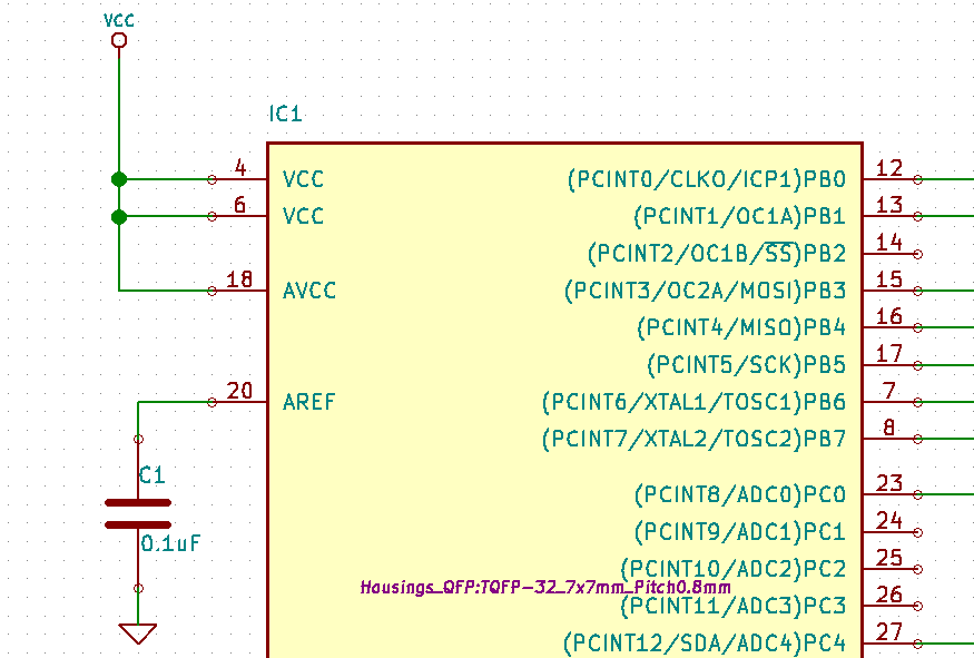 AVCC and AREF are the analog input voltage and external analog reference pins respectively. If you aren’t measuring analog signals with the onboard Analog-to-Digital Converter (ADC), you’ll need to connect AVCC to VCC, as I did above. If you are using the ADC, you’ll need to connect VCC to AVCC with a low-pass filter on AVCC. Folks on the forums suggest just a 0.1 [uF] capacitor from AVCC to GND.
the AREF pin is for providing an external analog reference for measuring analog signals. (This method must be enabled in software and defaults to using the internal reference.) My circuit above didn’t use the external analog reference, so the AREF pin could’ve been left floating. If you do use the AREF pin, you’ll want to create a reference voltage value on that pin by means of a voltage divider or some other method.
That’s about it! Make sure your board has a source of input power that falls below the maximum operating voltage (+6[V]), and you should be good to go!
Cheers–and best-of-luck making your own clones!